In addition to viewing the Assembly and Installation Manual you can set up a time to see the assembled equipment in operation at Alpine Solar Heat and Hot Water in Windsor, Massachusetts. The manual for Sunflower controller Model SR868C8 is available as a PDF file. If you send a request by email to the address at the top of the page or in the sidebar, the file will be sent to you.
 fig. 1

fig. 2

fig. 3
Assembly:
1. Install 30 clamps (part no. 6) on the horizontal clamp bar (part no. 3), fig. 1. [Note: This step could be completed after the frame is mounted to the roof, wall, or ground if there is easy access.]
2. Use six Hex Machine Screws (part no. 9) to attach three Vertical Struts (part no. 2) to the Manifold Box (part no. 1), fig. 2 and fig. 3. [Note: Screws are metric.] First remove the screws from the Manifold Box, then insert each screw through the tab on the Vertical Struts and into the Manifold Box. It may be necessary to bend the tab with pliers to obtain a 90 degree angle.
3. Attach the horizontal clamp bar (part no. 3) to the ends of the Vertical Struts using Hex Machine Screws & Nuts (part no. 8), fig. 3.
Mounting and Plumbing:
4. The assembled frame can now be attached to the roof, wall, or ground mount. An additional mounting kit is available to help obtain the desired tilt angle. Be sure to use only stainless steel hardware. [Note: Galvanized or steel mounting hardware will react with the stainless steel frame and cause rapid corrosion and deterioration.] If using the tilt mounting bracket (assembly instructions on the next page), it works well to assemble the mounting kit then attach the mounting bracket to the collector before carrying them up a ladder.
5. Complete all plumbing and control wiring after the frame is mounted. Plumbing should contain all safety measures including but not limited to: expansion tank, expansion joints for long pipe runs, air escape (bleeder), and high temperature/high pressure relief valves. Piping should be flushed to remove any flux or dirt.
The controls must be operational, and set to circulate fluid (usually water antifreeze mix) through the collector when it receives heat from the heat pipes in the evacuated tubes. THIS MUST BE DONE BEFORE INSERTING THE GLASS TUBES. Transferring heat to the circulating fluid will help avoid extreme temperatures, which could ruin the equipment.
Evacuated Tube Insertion:
6. Place a Rubber Boot (part no. 5) on the end of each Glass Tube with Heat Pipe (part no. 10), fig. 4.
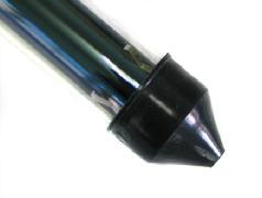
fig. 4

fig. 5

fig. 6
7. Coat the protruding copper end of the Heat Pipe with Thermal Silicon Grease (part no. 7). An acid brush, shown at the bottom of fig. 7, can be used to spread the grease on the contact surface of the heat pipe. Push the tube into the manifold box, fig. 5, (a slow rotating motion may help) then tighten the screw on the Clamp (part no. 6). The clamp will hold the rubber boot and bottom of the tube, fig. 6. The tube will slide in easier if soapy water is first brushed onto the Rubber Cap (part no. 4). A dish mop and a dish mop with extended handle are shown in fig. 7. The longer handle is convenient since the installer will be at the bottom of the collector to tighten the clamps.

fig. 7
Repeat until all 30 tubes are installed.
